In order to draw a spanner in engineering drawing pdf, you will need to first sketch out the basic shape of the object. Next, use a ruler or other straight edge to draw the lines representing the sides of the spanner. Finally, add in any details such as the screws or other markings.
There isn’t a definitive answer to this question since it can vary depending on the spanner’s size and shape. However, a few tips on how to draw a spanner in engineering drawing pdf would be to first lightly sketch out the outline of the spanner. Next, add in the detailing such as the spanner’s teeth and any other markings. Finally, use a thicker line to darken the drawing and make it stand out.
How do you draw a spanner?
And then what we do is we draw a little line down where those two circles meet. And then we just fill it in, and that’s how you make a cat.
Construction lines are used to help sketch out the basic shape of an object. Visible object lines are used to draw all the edges of the object. Hidden object lines are used to help show the center of an object. Extension lines are used to help show the dimensions of an object.
What are the 6 types of engineering drawing
Engineering drawing and sketching are the two main methods used by engineers to communicate their ideas. Both methods have their own advantages and disadvantages, and which one is used depends on the specific situation.
Isometric drawing is a type of three-dimensional drawing that shows an object from a single view. It is often used to show how an object will look when it is assembled, or to show the internal structure of an object.
Orthographic or multiview drawings are two-dimensional drawings that show an object from multiple views. They are often used to show the different parts of an object, or to show how an object will look when it is assembled.
Dimensioning is the process of adding measurements to a drawing. This is often done to show the size of an object, or to show the tolerances that are allowed for an object.
Sectioning is the process of cutting an object in half to show its internal structure. This is often done for objects that are too large to be drawn in full, or for objects that have an intricate internal structure.
Drawing tools are the tools that are used to create a drawing. These can include pencils, pens, rulers, and software programs.
Assembly
There are many types of technical drawings, and each has its own purpose and standards. 3D drawings can be used for isometric or perspective views, while exploded-view 3D drawings show the components of an object in a separate, exploded view. Complete working drawings show all the necessary information for constructing an object, while detail drawings focus on specific parts or features. Diagrams are another form of technical drawing that can be used to show the relationships between parts or systems.
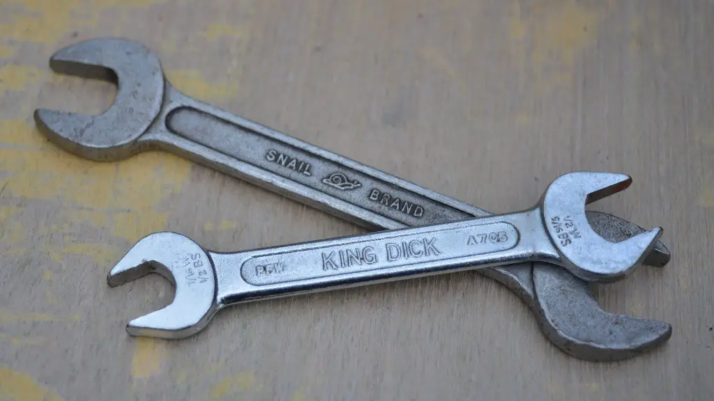
What shape is a spanner?
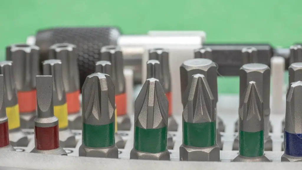
There are two types of wrenches: L-shaped and T-shaped. L-shaped wrenches are made from hexagonal wire stock, while T-shaped wrenches have a metal or plastic handle attached to the end. There are also indexable-driver-bits that can be used in indexable screwdrivers.
Spanner wrenches come in a variety of shapes and sizes, each designed for a specific purpose. The most common type of spanner wrench is the C spanner, which is designed for use with nuts of a similar size. Other types of spanner wrenches include the D spanner, which is designed for use with bolts, and the E spanner, which is designed for use with screws.
What are the 12 line types?
1. Visible Lines
Visible lines are the lines that are actually drawn on the engineering drawing. These are the lines that show the shape and size of the object.
2. Hidden Lines
Hidden lines are the lines that are not drawn on the engineering drawing. These lines are used to show the hidden features of the object.
3. Section Lines
Section lines are the lines that are used to show the cross section of the object.
4. Center Lines
Center lines are the lines that are used to show the center of the object.
5. Dimension Lines
Dimension lines are the lines that are used to show the dimensions of the object.
6. Extension Lines
Extension lines are the lines that are used to extend the lines of the object.
7. Leader Lines
Leader lines are the lines that are used to show the connection between the lines of the object.
8. Cutting Plane Lines
Cutting plane lines are the lines that are used to show the cutting plane of the object.
9. More items
There are other types of lines that are used in engineering drawing, such as:
10. Break Lines
Break lines are the lines that
There is no substitute for hard work and practice if you want to improve your skills. You need to be dedicated and consistent in your efforts, even if it’s just for a few minutes each day. Keep at it and you will see results!
What are the four 4 basic kinds of lines in drawing
There are various types of lines that can be distinguished based on their orientation or relationship to other lines. Horizontal lines are lines that are parallel to the horizon, while vertical lines are perpendicular to the horizon. Parallel lines are lines that are parallel to each other, while perpendicular lines are lines that intersect at right angles.
Engineering drawing is a tough subject, but it is one of the most important parts of engineering. A sound knowledge of drawing is vital to success in this field.
What are the 4 basic drawing techniques?
When starting to draw, it is important to find a technique that works for you. Some basic techniques that may help include back and forth movements, hatching, cross hatching, and scribbling. Experiment with each to see what you are most comfortable with. With time and practice, you will develop your own unique style.
Artistic drawings are usually done by hand and focus on the aesthetics of the piece. Technical drawings are usually done with software and focus on the functionality of the piece.
Is technical drawing difficult
Technical drawing is a freehand graphical representation of an object, usually to scale. It requires a lot of practice to produce clean, precise drawings. When multiple rough sketches are required, it is even more important to have mastered the various lines and how to enrich them.
Technical drawings are more straightforward than artistic drawings – they have one intended meaning that is typically understood by whoever is viewing the drawing. On the other hand, artistic drawings can be subjectively interpreted; their meanings are multiply determined based on the viewer’s own personal understanding and context. Either way, a drafter, draftsperson, or draughtsman is responsible for creating the drawing.
What is the difference between technical drawing and engineering drawing?
Technical drawings are essential for communicating detailed information about an object or structure. They are typically used by engineers, electricians, and contractors as guides when constructing or repairing objects and buildings. Technical drawings are usually created using specialized software, and they must adhere to specific standards in order to be effective.
It looks like a car with a spanner through it remains illuminated when you’ve started the ignition to signify that your car is due for a service. In this case, you should book your car in for servicing as soon as possible.
Warp Up
There is no one definitive answer to this question. However, a general overview of the steps involved in drawing a spanner in engineering drawing pdf format can be found in many online tutorials or textbooks on the subject. In general, the process involves creating a basic outline of the spanner shape, adding dimensions and annotations, and then refining the drawing with shading and other details.
A spanner is a type of wrench that is used to turn nuts and bolts. In order to draw a spanner in engineering drawing pdf, you will need to use a few basic shapes. First, draw a rectangle that will be the body of the spanner. Next, add two oval shapes for the handles. Finally, add a rectangular shape for the jaws of the spanner.
